Specifications
Fiberglass (FRP) Column Cover Specifications
SECTION 06610

Columns Details
(141 KB)
Columns - Column Covers
(442 KB)
Columns - Capitals
(385 KB)

Columns - Capitals
(616 KB)
Columns Details
(233 KB)

Columns Details
(48 KB)
Columns - Column Covers
(480 KB)
PART 1- GENERAL
- RELATED DOCUMENTS
- Drawings, conditions of the contract and Division 1 Specifications sections, apply to work of this section.
- SUMMARY
- Section Includes: Architectural Fiberglass Reinforced Polymer (FRP) Column Covers.
- RELATED SECTIONS
- Section 05120 — Structural Steel: Support framing for architectural fiberglass column cover.
- Section 06100 — Rough Carpentry: Framing of Opening and Blocking.
- Section 07900 — Joint sealants and field applied sealants.
- DESIGN REQUIREMENTS
- Installed architectural fiberglass column covers and fastening systems shall be designed, engineered, fabricated, and installed to conform to the state codes, local codes, and the Architect’s design.
- SUBMITTALS
- Shop Drawings: Shall illustrate dimensions, adjacent construction, materials, thickness, fabrications details, required clearances, field jointing, tolerances, colors, finishes, methods of support, attachments, anchorage to substrates, integration of components, and list of part numbers that coordinate with labeled architectural column covers.
- Submit manufacturer’s current valid certification with The Certified Composites Technician (CCT) program created by the American Composites Manufacturers Association (ACMA).
- Submit manufacturer’s internal Quality Control & Assurance Procedures based upon provisions published in the “Guidelines and Recommended Practices for Fiberglass Reinforced Plastic Architectural Products” upon request.
- Product Data: Submit manufacturer’s product data and installation instructions.
- Product Samples: Submit minimum 3-inch x 5-inch samples in specified color, texture and finish when applicable.
- QUALITY ASSURANCE
- Obtain architectural fiberglass column covers from a single source manufacturer that has the ability and resources to comply with the requirements and schedule of the project.
- Manufacturer to comply with Quality Control & Assurance Procedures, and fabricate architectural fiberglass based upon provisions published in the “Guidelines and Recommended Practices for Fiberglass Reinforced Plastic Architectural Products”.
- Inspect each molded piece to ensure that it complies with specified requirements, including nominal dimensions.
- MANUFACTURER’S QUALIFICATIONS
- Manufacturer: Provide products manufactured by a firm specializing in the manufacture of fiberglass architectural ornamentation, in the United States with a minimum of ten (10) years experience.
- Manufacturer shall demonstrate current valid certification and participation in the CCT program and fabricate material based upon provisions published in the “Guidelines and Recommended Practices for Fiberglass Reinforced Plastic Architectural Products”.
- Provide a list of projects comparable in size, scope, and complexity as indicated, upon request.
- Provide verification that architectural fiberglass (FRP) column cover meets or exceeds products specified.
- DELIVERY, STORAGE AND HANDLING
- Handle, store and transport architectural fiberglass column covers according to manufacturer’s recommendations and in a manner that prevents damage.
- Protect architectural fiberglass column covers from damage by retaining shipping protection in place until installation.
- Damage Responsibility: Except for damage caused by others, the installer is responsible for chipping, cracking, or other damage to fiberglass fabrications, after delivery to the jobsite and until installation is completed and inspected and approved by the Architect or owner’s representative.
- WARRANTY
- Warrant architectural fiberglass column covers to be free from defect due to materials and workmanship for one year.
PART 2 - PRODUCTS
- ACCEPTABLE MANUFACTURER
- Architectural Fiberglass, Inc.
8300 Bessemer Ave, Cleveland, Ohio 44127
Toll Free 1-888-483-1775
Phone 216-641-8300
Fax 216-641-8150
- Architectural Fiberglass, Inc.
- PATTERNS/MOLDS
- Custom Pattern/Mockups: Patterns and mockups shall be hand carved and/or CNC machined by skilled pattern makers with minimum of ten (10) years experience with architectural elements. Patterns & mockups shall be available at manufacturing facility for architect’s inspection and approval before molds are produced.
- Custom Molds: Molds shall be produced with ample layers of tooling resin, tooling gel-coat, glass fibers and/or flexible rubber by skilled mold makers with minimum of ten (10) years experience with architectural elements. Produced molds shall have rigidity and thickness to prevent distortion and deflection of molded architectural fiberglass.
- MATERIALS CHARACTERISTICS
- MOLDED EXTERIOR SURFACE:, NPG-ISO polyester gel coat, 18 to 22 mils thick. Gel coat shall be sandable grade for acceptance of finish paint. (Insert custom colored U-V inhibited gel coat when custom gel coat finish is specified.)
- BARRIER COAT: Specifically formulated backup polyester surface veil 18-20 mils thick to prevent glass print through and ultimate Class A finish.
- BACK UP LAMINATE:
- Resin: Polyester resin shall be fire retardant, and meet Class 1 flame spread rating of 25 or less as characterized by the ASTM E-84 tunnel test at typical 1/8″ glass mat laminate.
- Filler: Functional filler to be added to resin matrix to minimize shrinkage, add stiffness, control opacity, add fire retardance, improve surface finish, minimize crazing, and control dimensional stability from weather extremes.
- Fiberglass Reinforcement: Type “E” fiberglass, glass cloth, matt and/or random chopped glass fibers. Glass content approximately 20% to 30%.
- Laminate Thickness: Nominal laminate shall be minimum 3/16″ thickness. Additional core reinforcements and/or sandwich structure added as required for rigidity and structural integrity.
- FABRICATION
- Column cover halves shall be manufactured with sufficient butt joints to provide structural integrity and shall be manufactured to accommodate construction adhesive, and align with adjoining half section. (Insert custom engineered lap or reveal joint when specified.)
- Column vertical joint shall be designed to accept polyester body filler for monolithic finish and field painting. (Insert that column vertical joint shall be caulked when custom reveal joint detail is specified.)
- Column cover shaft half sections shall be manufactured as a single unit spanning entire height from base to top of capital.
- Column base shall be manufactured as a separate unit for column shaft height adjustment.
- AVERAGE MECHANICAL PROPERTIES:
Tensile Strength: 12,000 PSITest method: ASTM D638
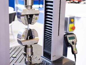
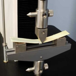
Flexural strength: 20,000 PSITest method: ASTM D790
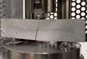
Flexural modulus:0.9x10⁶ PSITest method: ASTM D790
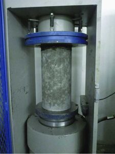
Compressive strength: 17,000 PSITest method: ASTM D695
Bearing strength: 9,000 PSITest method: ASTM D638
Thermal expansion 10 x 10-6 (° F)
Specific gravity 1.5
- FINISH
- Color as selected by Architect for field painting unless otherwise specified. (Insert custom colored gel coat finish when specified.)
- Surface Texture/Exposed side shall be smooth ready for light sanding and painting. (Insert texture of custom finished gel coat when specified.)
- TOLERANCES
- Part Thickness: + or − 1/8 inch.
- Gel Coat Thickness: + or − 2.5 mils.
- Length: + or − 1/8 inch.
- Variation from Square: 1/8 inch.
- Hardware Location Variation: + or − 1/4 inch.
- IDENTIFICATION
- Identify each column cover unit with a permanent serial number.
- Number parts to coordinate with shop drawings.
- CURING AND CLEANING
- Cure and clean components prior to shipment and remove material which may be:
- Toxic to plant or animal life.
- Incompatible with adjacent building material.
- Cure and clean components prior to shipment and remove material which may be:
- ANCHORS AND FASTENERS
- Contractor to provide anchors and fasteners and other accessories for proper installation of architectural fiberglass column covers as recommended and approved by fiberglass fabrication manufacturer.
PART 3 - EXECUTION
- PRE-INSTALLATION EXAMINATION
- Carefully observe and verify field conditions that substrates are ready for installation of architectural fiberglass column covers. Contractor shall verify on site dimensions with shop drawings and assume full responsibility for fitting the components to the structure.
- Verify that bearing surfaces are true and level.
- Verify that support framing has been constructed to allow accurate placement, alignment and connection of architectural column covers to structure.
- Report discrepancies between design dimensions and field dimensions, which could adversely affect installation, to the Architect and/or Owner’s Representative.
- Do not proceed with installation until discrepancies are corrected, or until installation requirements are modified and approved by the Architect and/or Owner’s Representative.
- Beginning of installation means acceptance of existing conditions and fiberglass materials.
- INSTALLATION
- Install architectural fiberglass column covers in accordance with manufacturer’s instructions and approved shop drawings.
- Fiberglass column cover vertical joint shall be field finished and painted per manufacturer’s instructions for monolithic appearance. (Insert that vertical joint shall be field caulked when custom engineered joint detail is specified.)
- ALLOWABLE TOLERANCES FOR INSTALLED UNITS
- Maximum offset from True Alignment: 1/4 inch in 20 feet.
- Maximum Variation from True Position: 1/2 inch in 20 feet.
- CLEANING
- Clean installed architectural fiberglass column covers using cleaning methods and material approved by manufacturer.
- PROTECTION OF INSTALLED FABRICATIONS
- Comply with manufacturer’s recommendations and instructions for protecting installed column covers during construction activities.
Download Drawings and Specifications
Columns Details
(141 KB)
Columns - Column Covers
(442 KB)
Columns - Capitals
(385 KB)
Columns - Column Covers
(480 KB)
Columns - Capitals
(616 KB)
Columns Details
(233 KB)
Columns Details
(48 KB)
Columns Details
(141 KB)
Columns - Column Covers
(442 KB)
Columns - Capitals
(385 KB)
Columns Details
(233 KB)
Columns - Column Covers
(480 KB)
Columns - Capitals
(616 KB)
Columns Details
(48 KB)